Testing interference in a wireless environment
By Rolland Zhang, Agilent Technologies
Tuesday, 27 November, 2012
In wireless systems, interference in the wireless channel can be quite problematic, degrading the reception of desired signals. It can originate from a variety of intentional, unintentional and incidental radiators and occurs in both licensed and unlicensed spectrum.
With the growing scarcity of radiofrequency spectrum and ongoing efforts to improve its use for the highest capacity and performance (eg, by sharing or re-use), wireless communication systems must now operate under a limited amount of radio interference. Unfortunately, as demand for spectrum increases, so too does wireless system interference.
As a result, the identification and reduction of interference has become absolutely essential to the proper operation of all wireless systems.
Of course, testing interference in a wireless environment is no easy task, demanding new measurement techniques and placing added requirements on existing measurement instrumentation. Addressing it effectively requires an advanced measurement tool like a high-performance spectrum analyser, to evaluate, monitor and manage the interference levels between various wireless systems.
Classifying interference
In wireless communications systems, many different kinds of interference may be encountered. Such interference is often classified as:
- In-band interference - an undesired transmission from a different communication system or unintentional radiator that falls inside the operating bandwidth of the desired system.
- Co-channel interference - a common type of radio interference stemming from another radio operating within the same wireless system.
- Out-of-band interference - originates from a wireless system designed to operate in an assigned frequency band but, due to improper filtering, nonlinearity and/or leakage, also transmits energy into the frequency band of another wireless system.
- Adjacent channel interference - the result of a transmission at the desired frequency channel producing unwanted energy in other nearby channels, usually within the same system.
- Uplink (reverse link) interference - interference affecting the base station receiver and associated communications from mobile devices to the base station.
- Downlink interference - interference corrupting downlink communications, typically between a base station and mobile device.
The class of interference affecting a wireless system is important since it helps dictate the engineer’s response. For example, out-of-band interference can occur when a poorly designed or poorly filtered transmitter creates harmonics that fall into a higher frequency band. Because of this, properly filtering out the harmonics of a transmitter is critical and necessary to ensuring that one wireless system does not affect another system operating in a higher frequency band.
Techniques for measuring interference
When a wireless system does not operate as expected and radio interference is suspected, a modern, high-performance spectrum analyser should be used to confirm the existence of undesired signals in the frequency channel of operation.
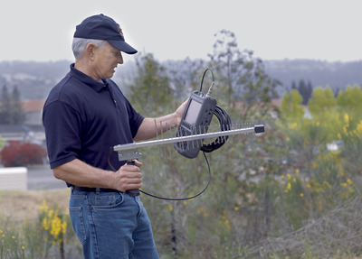
Such tools are extremely useful for measuring the power levels of interfering signals as a function of time, frequency and location. Since interference testing often requires measurement and data collection in the environment surrounding a wireless system, a lightweight, battery-operated instrument with performance consistent with traditional benchtop instrumentation is highly recommended (Figure 1).

The process of identifying undesired signals may involve uncovering the type of signal, including: its duration of transmission, number of occurrences, carrier frequency and bandwidth, and possibly even the physical location of the interfering transmitter. If the system operates in full-duplex mode, it may also be necessary to examine the uplink and downlink frequency channels for signs of interference.
Measuring interference, especially over the air, typically requires a spectrum analyser with a very low noise floor or DANL (displayed average noise level). The DANL is a function of the resolution bandwidth (RBW) setting with smaller values resulting in lower noise. A typical reduction in RBW by a factor of 10 results in a 10 dB improvement in noise floor.
The analyser’s measurement sweep time is an inverse function of the RBW. Therefore, longer sweep time is required with smaller RBW settings. As the ability to quickly measure and display a low-level signal is a function of the signal-to-noise ratio (SNR) at the detector of the analyser, improving the signal level can be achieved by reducing the amount of input attenuation on the analyser. With a lower value for input attenuation, typically down to 0 dB, it may be possible to increase the RBW, resulting in faster sweep times. The measured signal level at the detector may also be improved by using a built-in or external preamplifier.
Special attention should be given to the analyser when reducing the input attenuation and measuring large amplitude signals. Large amplitude signals can overdrive the analyser’s frontend, resulting in internally generated distortion or instrument damage. The internally generated distortion is displayed by the analyser as if it were coming from the signal-of-interest. Under these conditions, the attenuator setting should be optimised for the highest dynamic range.
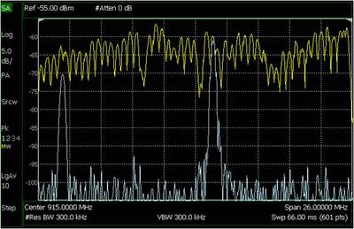
When measuring interference that is pulsed, intermittent or frequency hopping, the spectrum analyser display can be configured a number of different ways to aid in the detection and identification of these signal types. In MaxHold mode, for example, the spectrum analyser display can store and display the maximum trace values over multiple sweeps (Figure 2). This mode is very useful when only the maximum amplitude of an intermittent signal is required. If the signal variation as a function of time is also required, a spectrogram or waterfall display mode can provide additional insight into the intermittent signal structure.

A spectrogram is a unique way to examine frequency, time and amplitude on the same display. It shows the progression of the frequency spectrum as a function of time where a colour scale maps to the amplitude of the signal. The Waterfall display provides a 3D colour-coded history of the amplitude levels as a function of frequency and time.
Zero span mode and sweep acquisition may also be useful when measuring intermittent interference. In the zero span mode, the centre frequency of the spectrum analyser is tuned to a fixed frequency and it sweeps in the time domain. The RBW filter is adjusted wide enough to capture as much of the signal’s bandwidth as possible without increasing the measurement noise floor to unacceptable levels. Sweep acquisition captures low-duty cycle pulses or intermittent signals by capturing entire quantities of time domain data at a time. Interfering signals that are difficult to detect can also be captured with proper settings of RBW, attenuation and the preamplifier on.
Understanding equipment requirements
Several main features of the spectrum analyser must be considered when interference testing in the field, including its portability and ruggedness. A long battery life with quick battery replacement, rapid turn-on from a paused state, built-in GPS, DC block and DC voltage source are other requirements for field testing. The DC voltage source, when used with an external bias tee, is especially useful for powering a low noise block (LNB) downconverter found in satellite applications.
Along with the high-performance spectrum analyser, a high-quality test cable is required for connecting the analyser to the system’s test port or to the test antenna. Properly maintaining the cable, including protecting and cleaning the connectors on both the analyser and cable, is vital for accurate and repeatable measurements.
The test antenna is another important part of the interference test components. It should be designed to cover the frequency range of interest, while also being portable and lightweight. Ideally, it should have characteristics similar to those used in the wireless system under investigation.
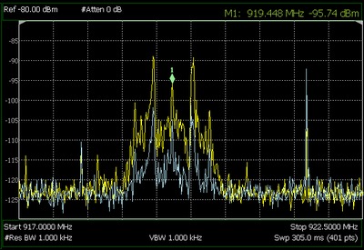
If the system antenna is a low-gain omnidirectional antenna with vertical polarisation, the antenna attached to the spectrum analyser should be the same (Figure 3). When examining the spectrum over a broad range of frequencies, a broadband whip-type antenna can be substituted for the typically narrowband system antenna.
When making measurements of very weak signals or when ‘direction finding’ unlicensed transmitters, a high-gain directional antenna should be attached to the analyser.

Figure 3: This over-the-air measurement, performed using FieldFox, compares the received signal using an omnidirectional antenna (blue trace) and a high-gain antenna (yellow trace). There is a noticeable increase in the measured amplitude of the unknown signal when using the high-gain antenna, but this measurement required the antenna to be pointed in the direction of the highest signal amplitude.
Summary
Given the growing demand for spectrum, wireless interference is sure to be an expanding problem. At best, the interference will impact only a small number of users, while at worst it will disrupt communication within the entire wireless system, making it all the more critical for engineers to effectively test for radio interference.
A modern, high-performance spectrum analyser can play a key role in accomplishing this goal. Selecting one that meets essential requirements for field testing and using it with a range of measurement techniques can be just as critical in ensuring a wireless system is not adversely affected by interference.
Ensuring 5G network performance
To be successful in business-critical use cases, the wireless networks need to be as reliable as...
Ubiquitous connectivity is the future of wireless
Systems capable of seamlessly using satellite, cellular and local area networks are nowadays a...
Benefits of advanced DC power management at tower sites
Comprehensive monitoring and control of the DC power at tower sites enhances the effectiveness of...


